Details:
Customer
![]()
PRODEA Investments
Technology Used
- Ansys SpaceClaim 25R1
- Ansys Fluent 25R1
Objective:
The study predicted airflow and temperature distribution in the external mechanical rooms of the residential and office buildings of 17-storey and 16-storey, respectively, "Landmark Towers" in Nicosia under hot summer conditions. The goal was to ensure that air-conditioning units located in mechanical rooms of each floor operate under acceptable conditions and draw in fresh air that is not "contaminated" by the recirculation of hot air rejected from other units of the same or adjacent floors. In order to achieve this, the simulation of a large air volume around the buildings, in addition to mechanical rooms volume, was necessary. Simulations revealed the great effect of the perpendicular louvers and covers, which greatly determine the airflow pattern and temperature distribution.
Challenge:
The primary challenge was to assess whether the external mechanical rooms allowed for proper ventilation and cooling of the hosted air-conditioning units (70 in Office and 71 in Residential buildings, respectively), given the extreme ambient temperatures and limited space. Specific challenges included:
- Verifying that hot air rejected from AC units does not recirculate into the intake of other units.
- Evaluating how architectural elements (louvers, covers, and surrounding structures) influence airflow direction and heat dissipation.
- Identifying potential thermal improvements without major architectural and structural modifications.
Solution:
To address these challenges, CFD simulations were conducted to evaluate the effectiveness of different design configurations:
- Office Building Analysis: The office building's external mechanical rooms were analyzed to verify thermal conditions. The simulations confirmed that the initial units arrangement provided adequate cooling without significant air recirculation issues.
- Initial Residential Building Analysis: The first simulation of the residential building revealed that hot air was recirculating into the air-conditioning units, leading to high intake temperatures beyond acceptable limits.
- Collaborating with PRODEA Engineers to Adjust the Design: Based on the findings, Simtec was engaged in discussions with PRODEA engineers to create an alternative configuration. This involved adjustments to unit placement and louvers orientation, which resulted in sufficiently improved airflow and reduced recirculation.
Louvers were modeled as "porous media". This "lumped-parameter" model accurately reproduces pressure drop and flow shift caused by the inclined blades, by providing values for the associated permeability and inertia coefficients, taken from detailed separate CFD simulations of the exact louver geometry. A similar approach was followed for the insect mesh attached at the inner side of the louvers. High-quality polyhedral meshes (12.5M cells for the residential building and 21M cells for the office building) were used, with local refinement near all walls and AC units intakes.
Conclusion:
The CFD analysis provided key insights into the thermal management of external mechanical rooms, ensuring efficient operation of air-conditioning units. The main findings were:
- Residential Building: The initial configuration resulted in excessive heat recirculation, causing high intake temperatures. An improved configuration was validated with CFD and successfully mitigated these issues.
- Office Building: The existing setup was found to be effective, without any overheating detected.
- Architectural Influence: The presence and orientation of louvers played a crucial role in airflow control, while covers assisted in shielding units from sucking hot recirculated air.
Ansys Fluent enabled the experienced Simtec analysts to assist PRODEA engineers in solving a difficult and multi–parametric technical puzzle in a complex building compound. The CFD model results led to necessary design modifications in an early project stage, avoiding post–construction operational faults which are very costly and margins for changes are very limited.
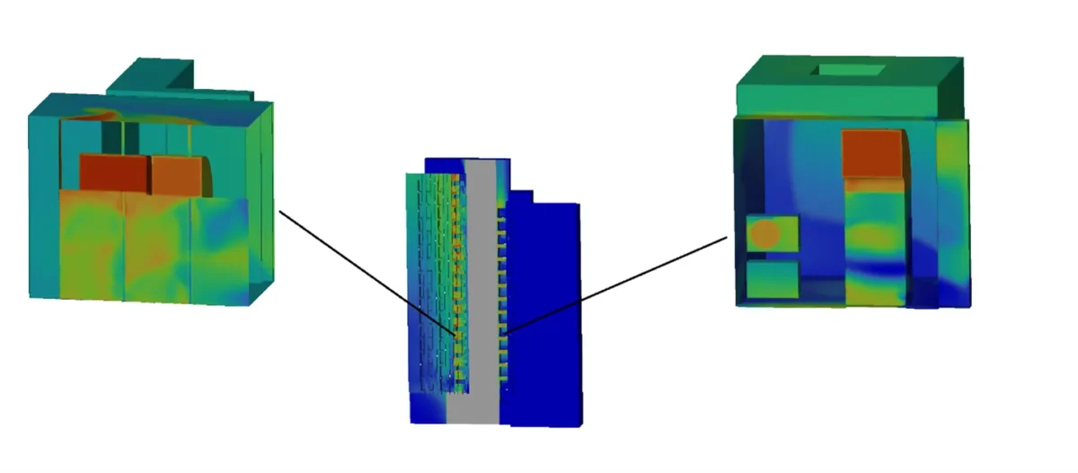
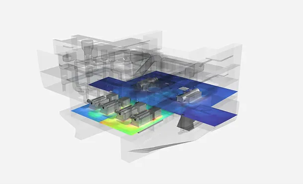
Figure 1: Temperature Distribution at Office Building Shell, Mechanical Rooms are located in the Middle.
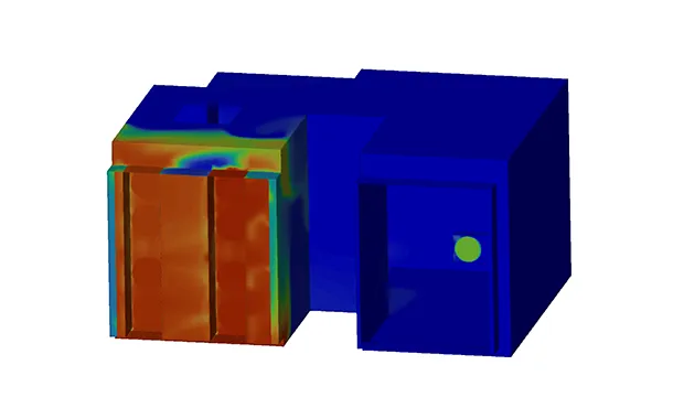
Figure 2: Temperature Distribution at Residential Building Shell. Mechanical Rooms are located in the Middle.
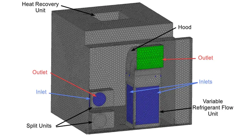
Figure 3: Surface Mesh on a Typical Mechanical Room of the Office Building.